My Individual Contributions:
• Design of the bottom rotary tool wheel (BTW) and its associated end-effectors
• Collaborated on design of Eater-Feeder subsystem, Top Tool Wheel (TTW), neck rack,
. and global system architecture
. and global system architecture
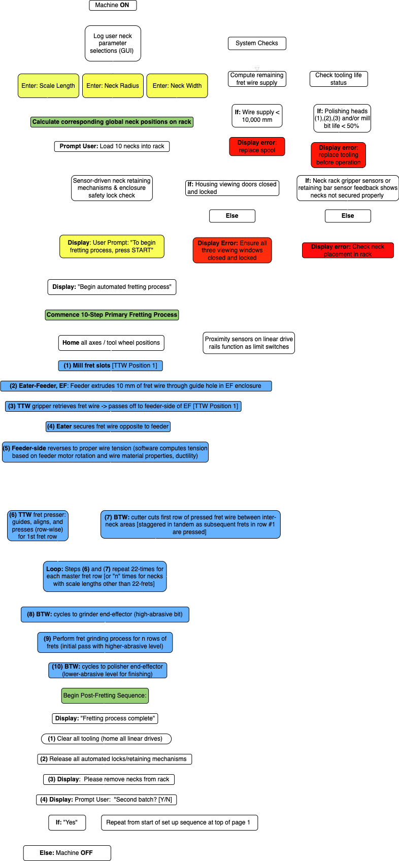
• Design of detailed process flowchart for machining, controls, and sensing operations
• Creation of the graphic user interface (GUI) in MATLAB
Background
Design Objective
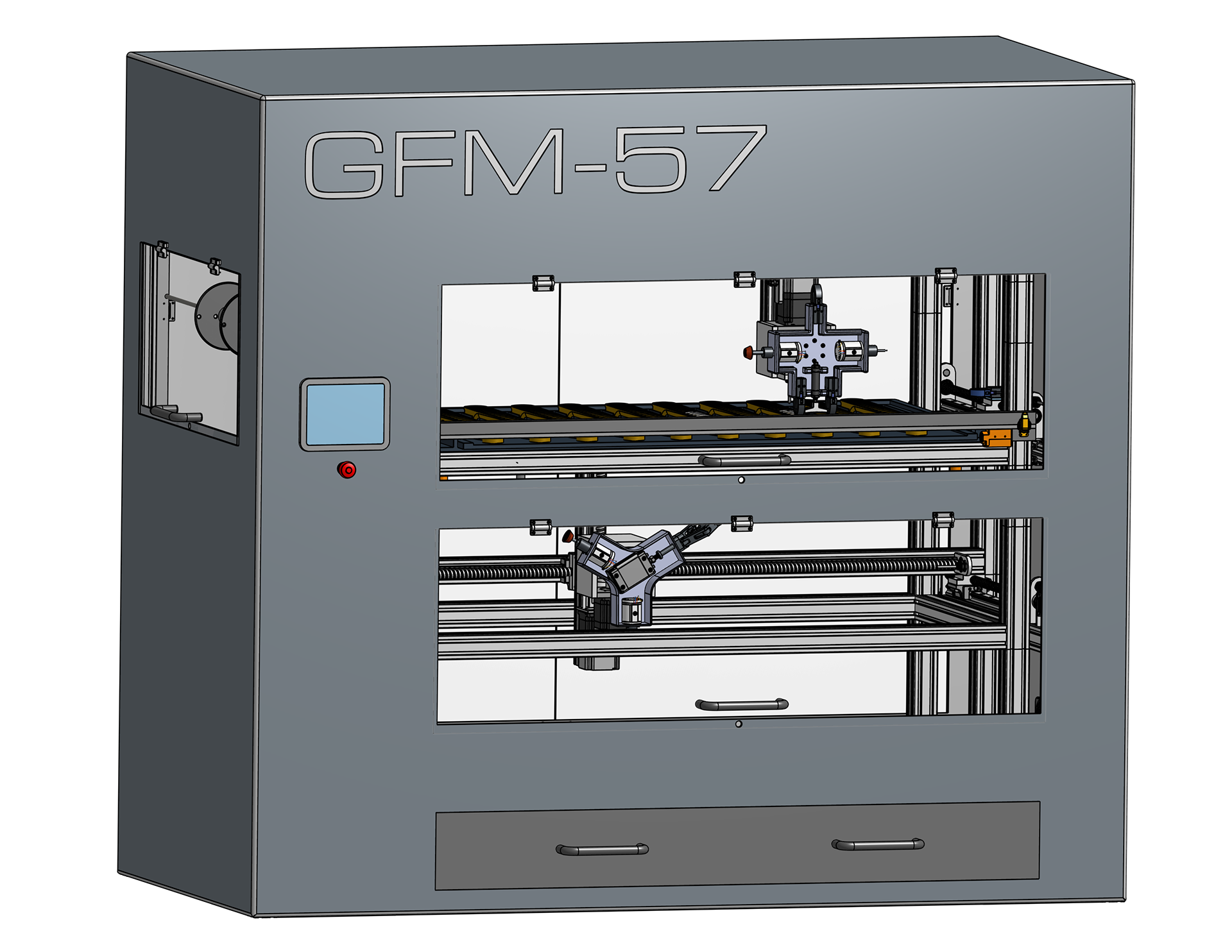
The purpose of this project was to design a fully-automated machine for fretting electric guitar necks.
Guitar fretting is a precise, multi-step process which includes milling 24 fret slots, pressing fret wire into the slots, cutting the fret wire, and finishing the ends of each fret so they sit flush with the neck profile
Problem Statement
The current industry standard is for skilled luthiers to perform guitar fretting manually, by hand. This is both time-consuming and labor-intensive. An automated precision machine that performs this process offers significant financial advantages to manual fretting, and offers a much higher throughput.
Top Tool Wheel (TTW) performing fret pressing
Design Selection
Design decisions for each machining process (e.g. neck rack loading, fret slot milling) were made by brainstorming feasible concepts as a group and evaluating them through Pugh charts; the highest-scoring design was then selected for development. Samples of concept generation and Pugh charts can be viewed in the PDR Presentation Slides download below.
Machine Subsystems
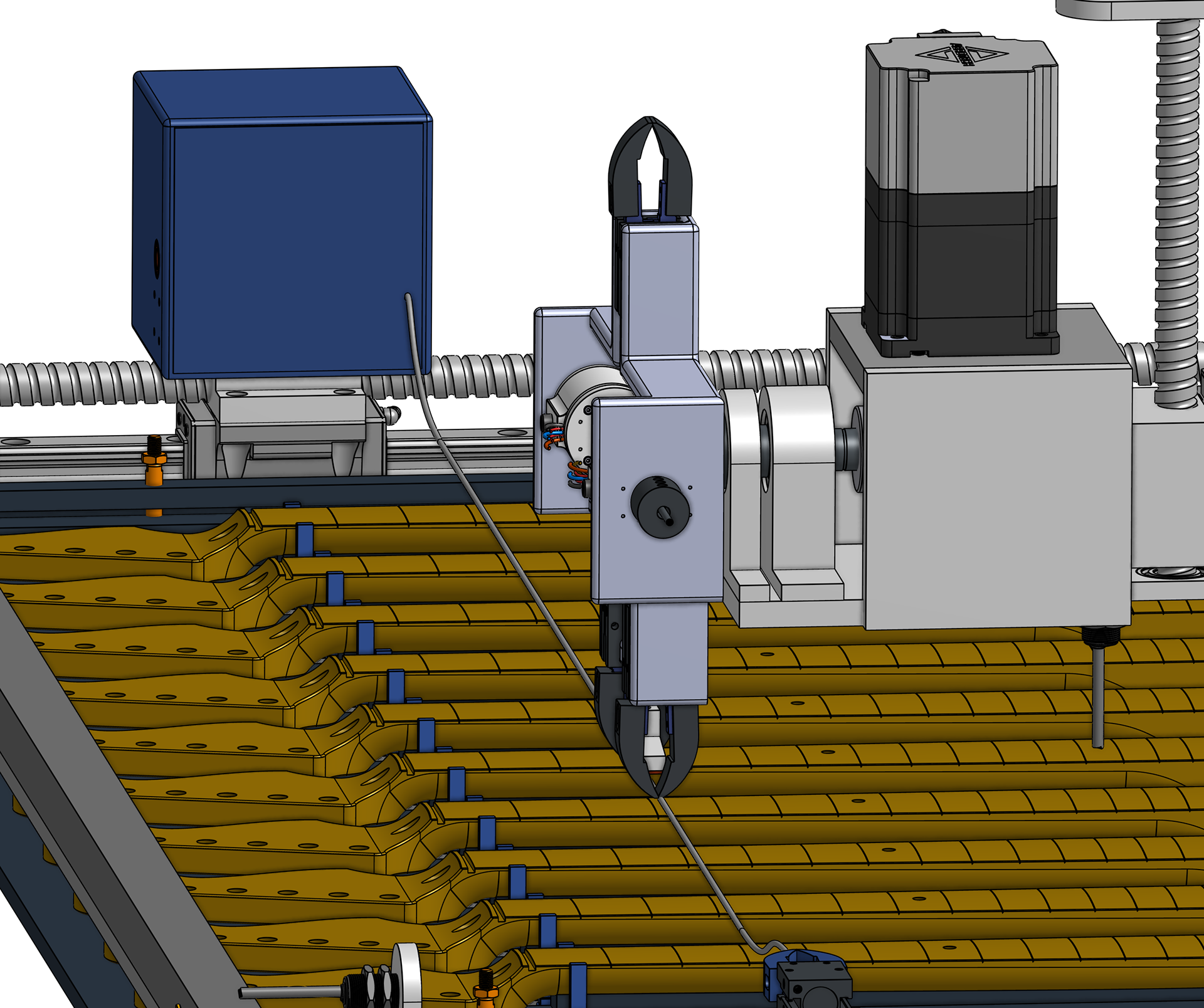
I. Eater-Feeder Fretting System
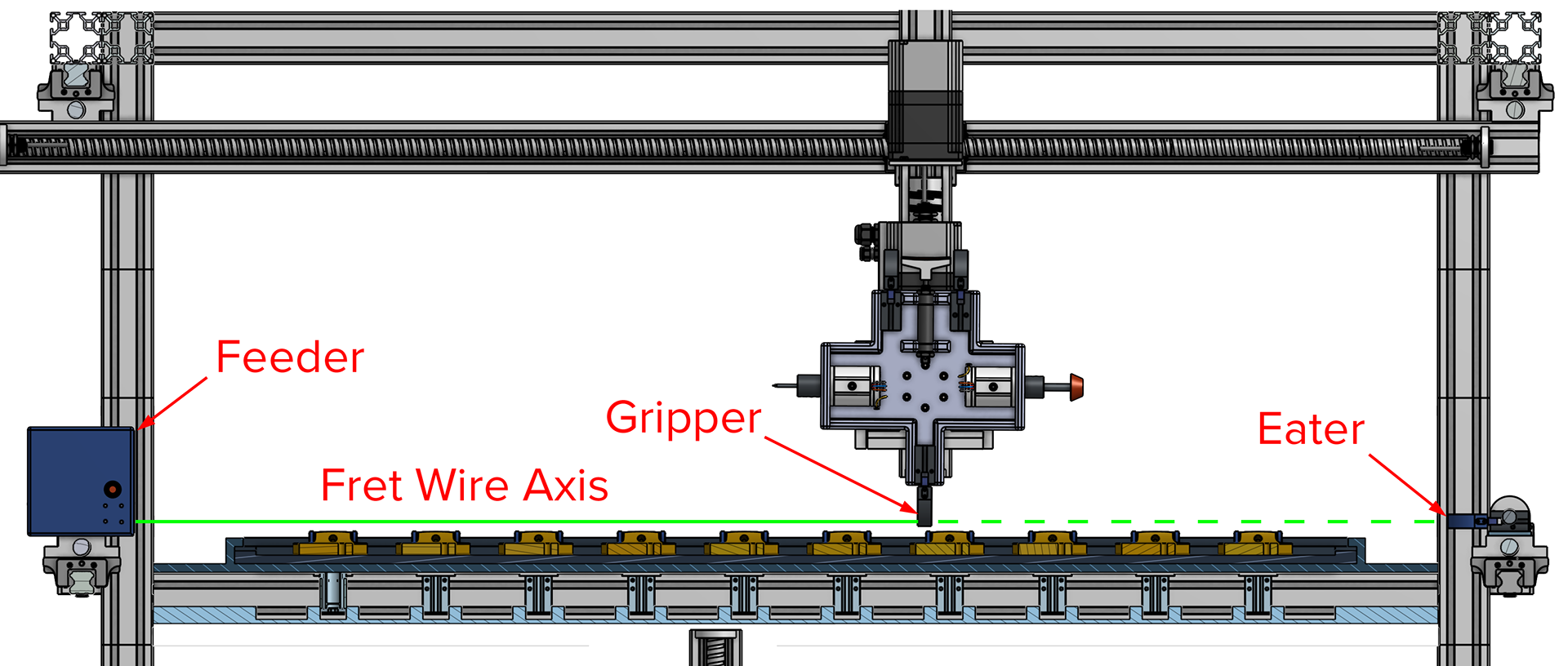
The Eater-Feeder system transfers the free end of the fret wire from the Feeder module to the Eater.
The gripper end-effector on the Top Tool Wheel (TTW) is used to perform this transfer, after which the Feeder module reverses to properly tension the fret wire. The fret wire supply spool is housed externally to the Feeder, which controls tensioning, feed rate, and alignment.
The Eater and Feeder then move in parallel to each other to position the wire length above the first row of ten frets, prior to pressing.
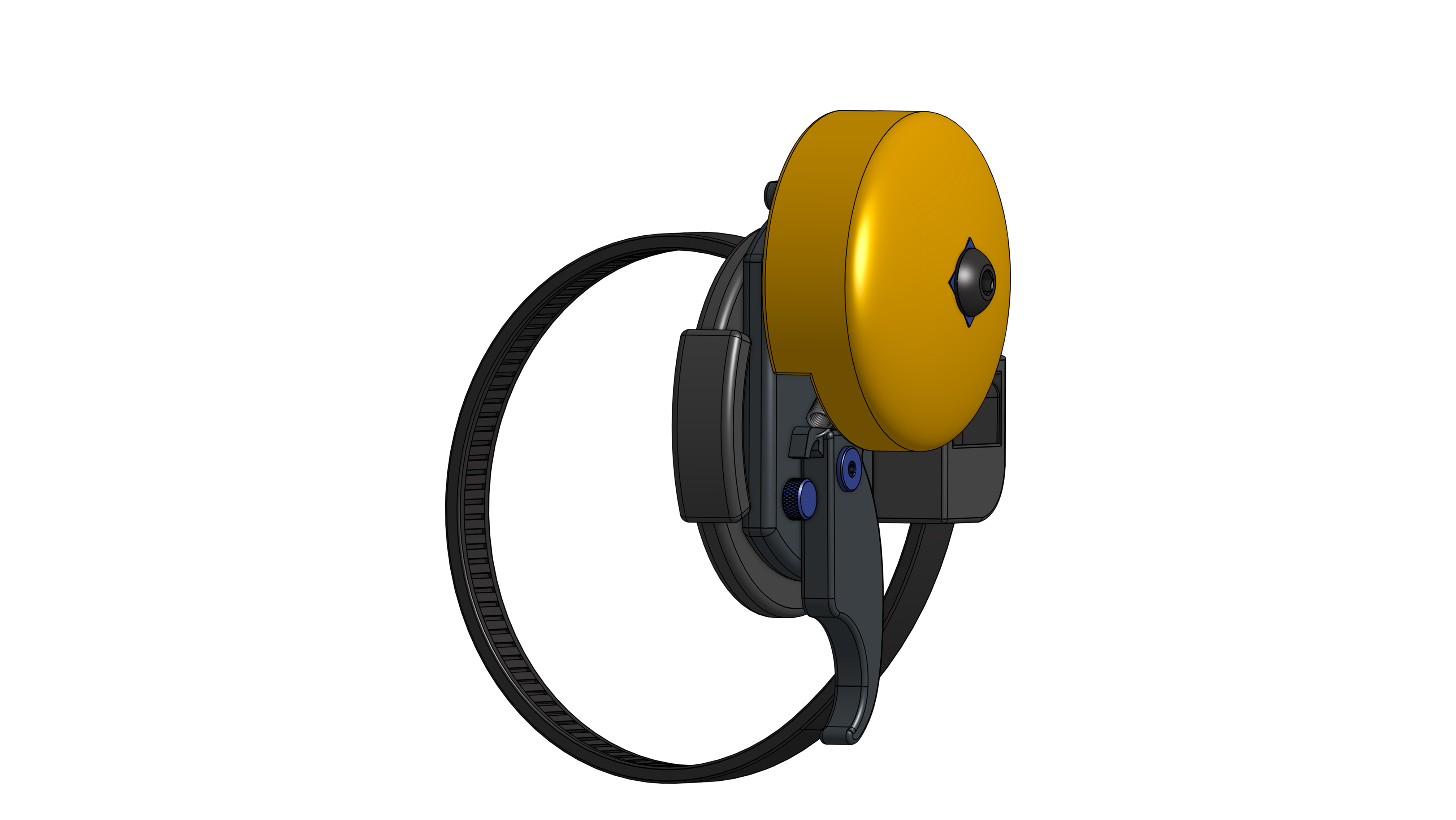
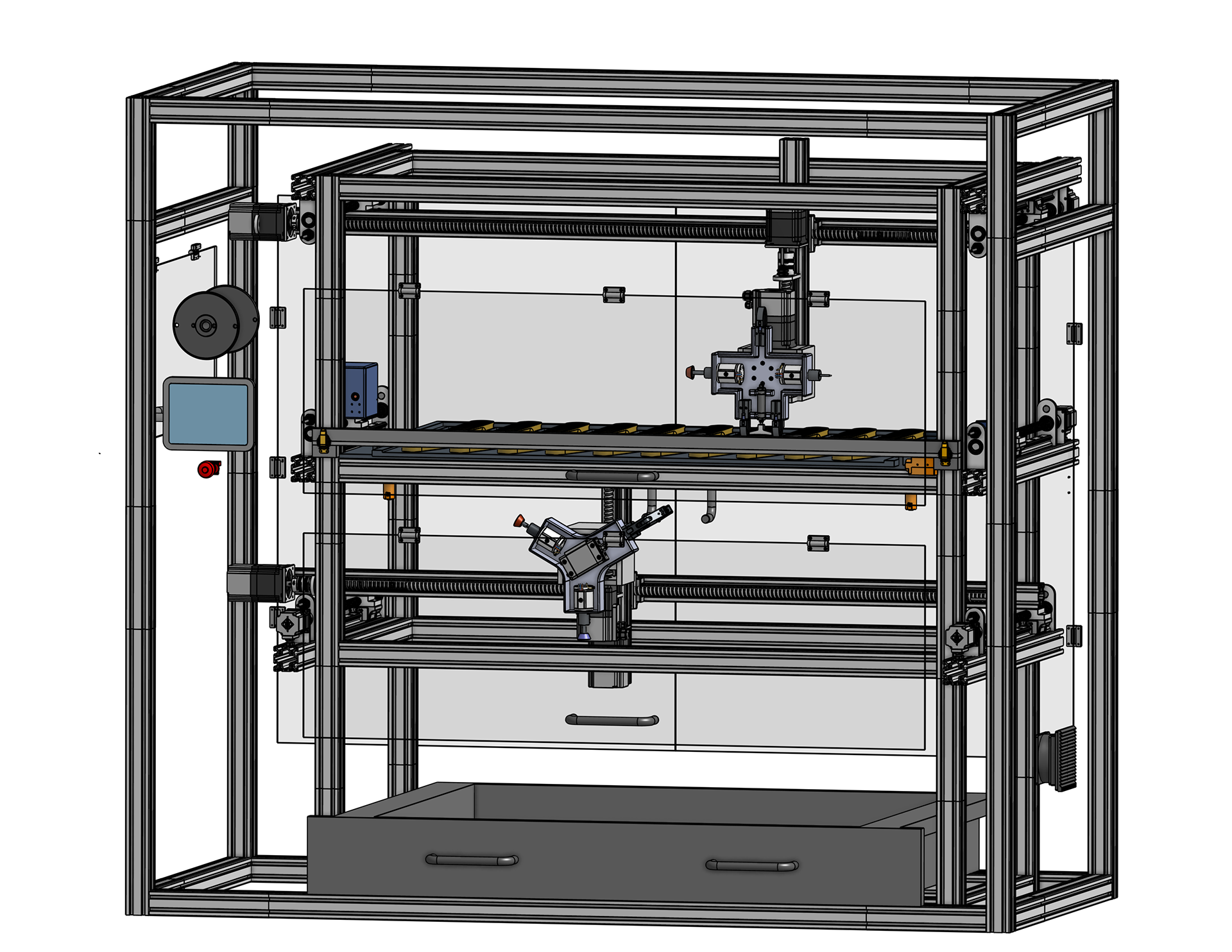
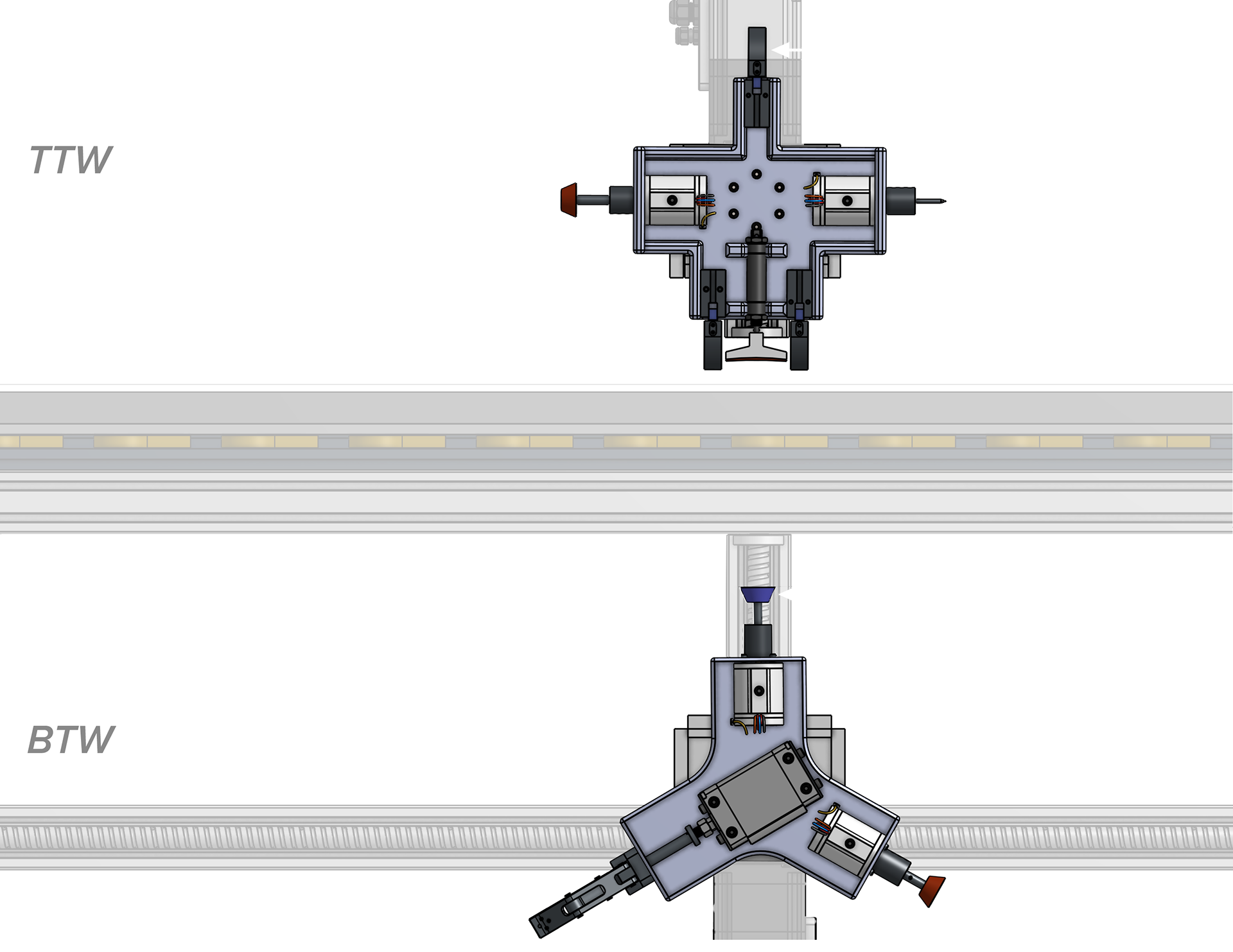
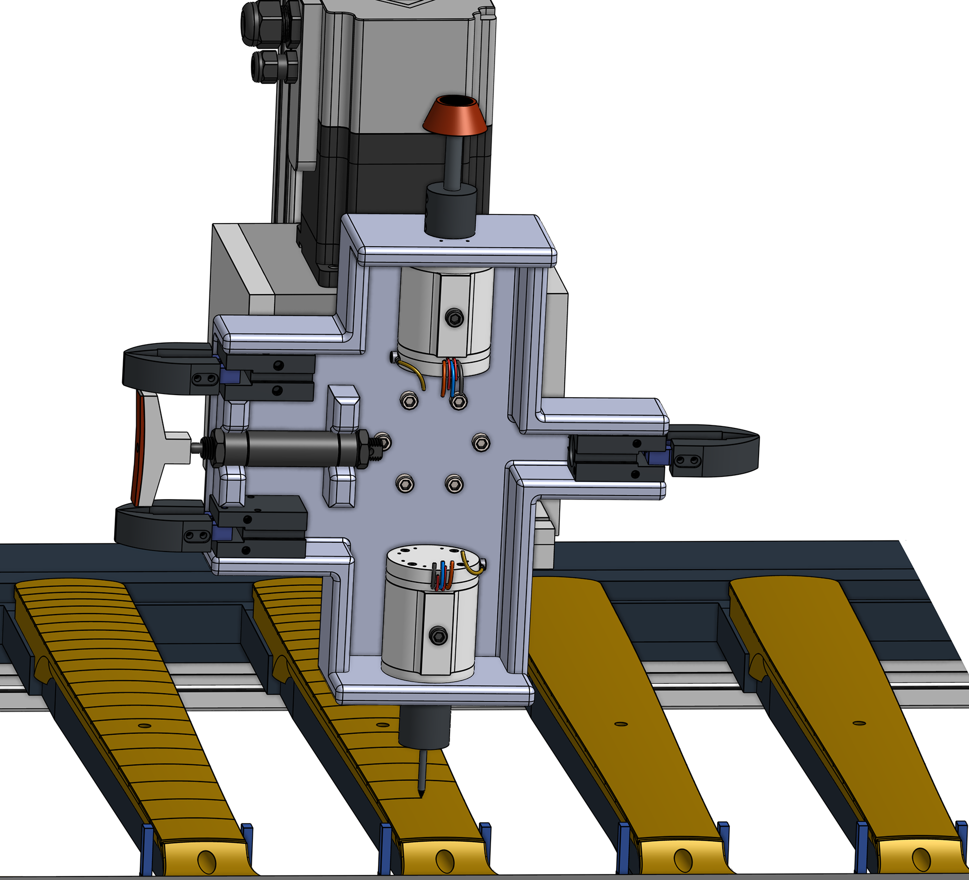
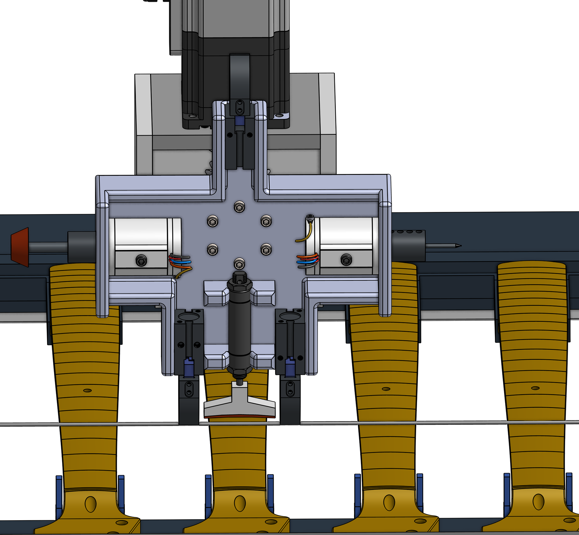
II. Top & Bottom Tool Wheels
Our design utilizes two rotary tool wheels, the Top Tool Wheel (TTW) and Bottom Tool Wheel (BTW).
These multi-purpose end-effector platforms cycle rapidly between tooling to perform each MFG process, while maintaining an efficient footprint within the build area.
The tool wheels perform some machining processes in tandem to minimize cycle time (see fret grinding below).
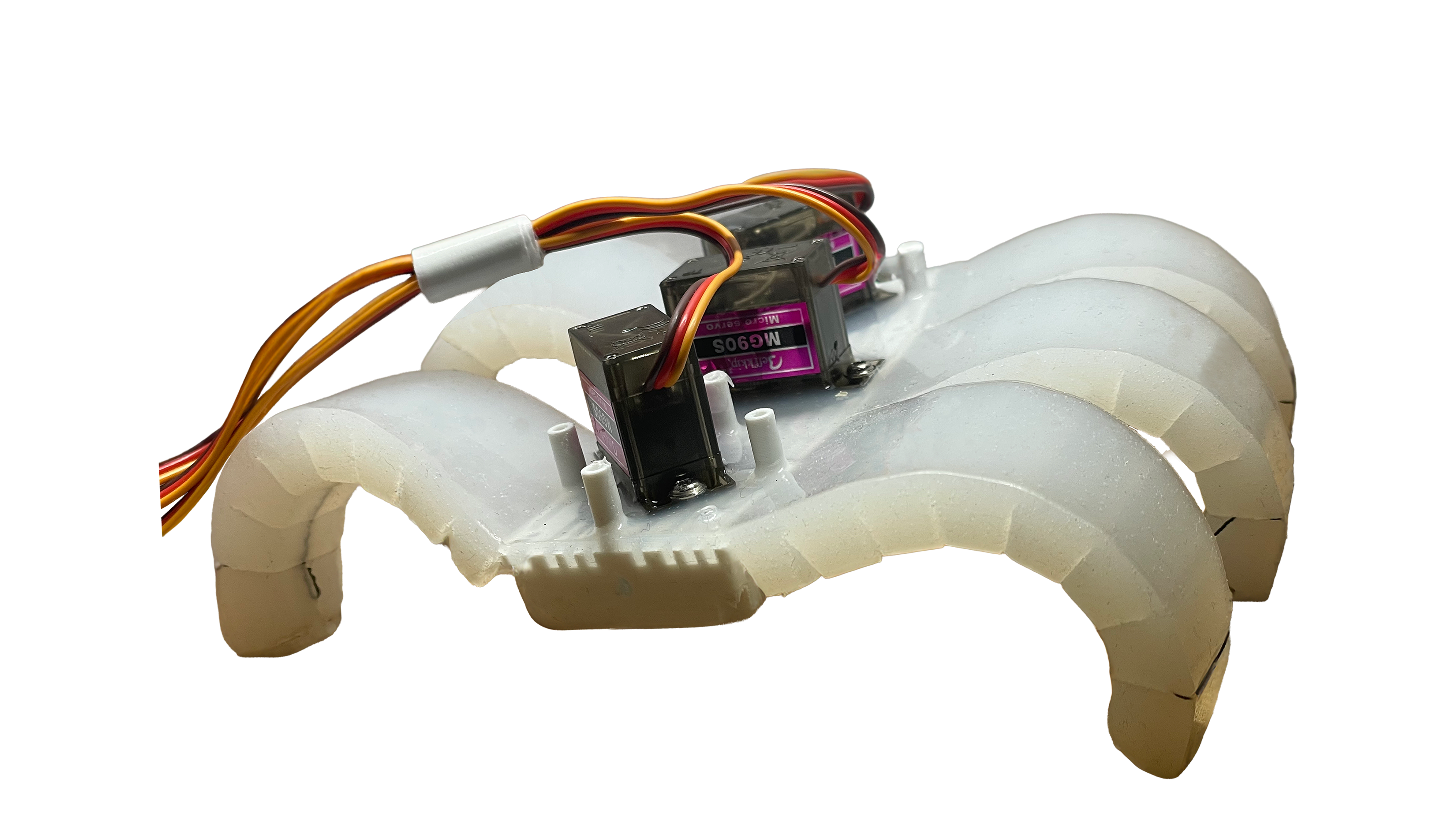
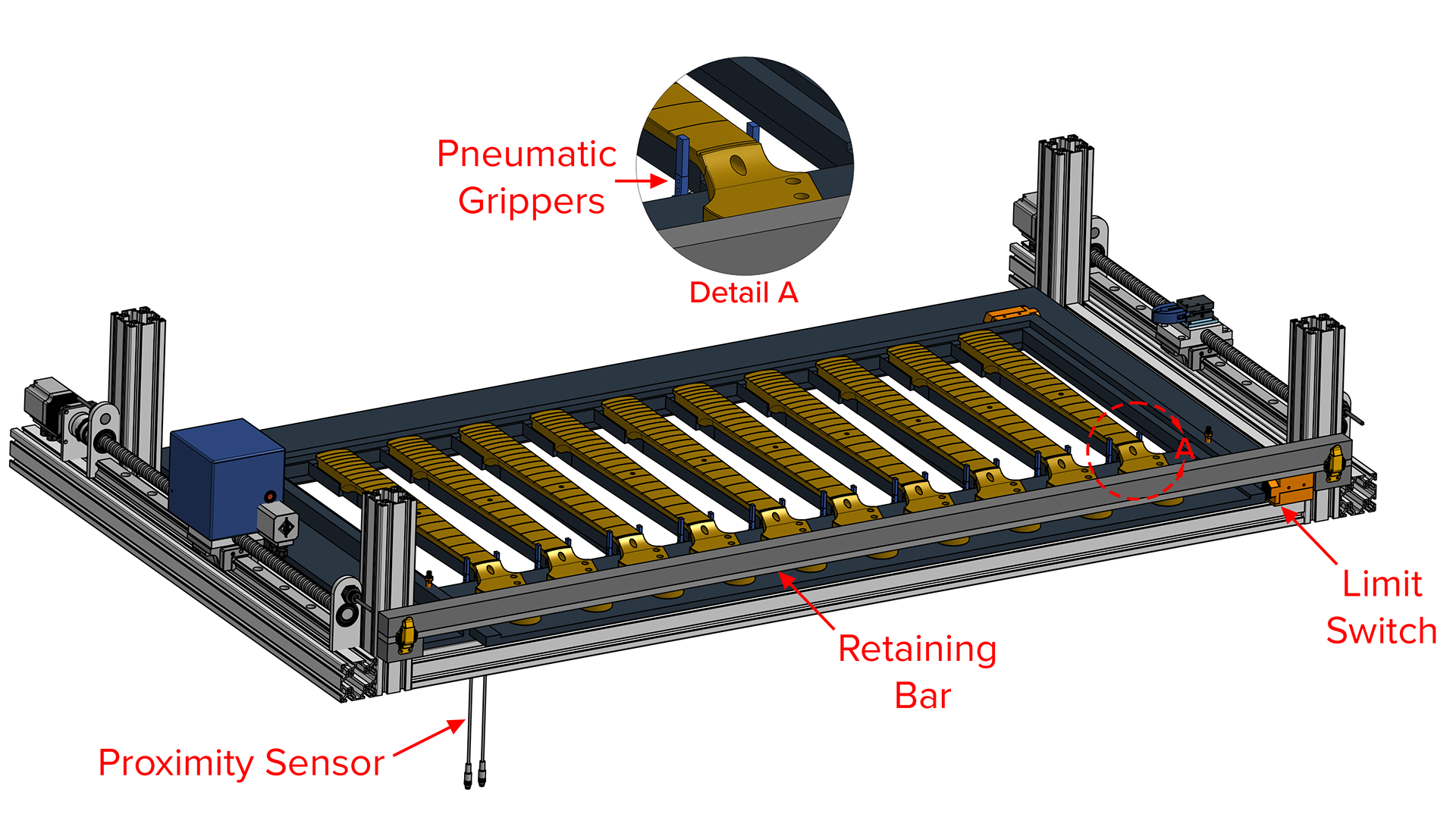
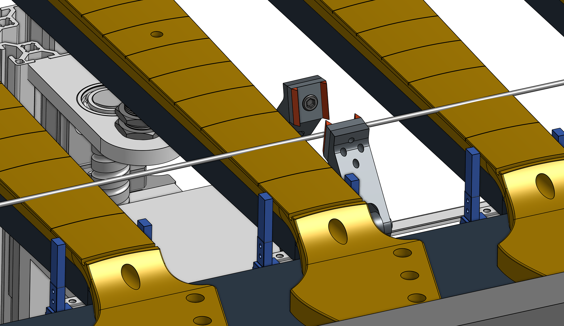
III. Neck Rack
The removable neck rack can accommodate guitar necks with varying scale lengths, radii, and fret board widths.
It achieves this through the use of adaptive retaining mechanisms, such as proximity sensor-equipped pneumatic grippers with compliant surfaces.
Machining Process Overview
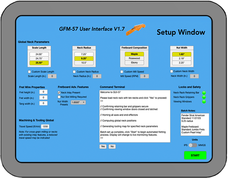
I. Batch Setup
The Graphic User Interface (GUI) Batch Setup Window prompts the user to select preset global neck parameters, such as scale length, neck radius, fretboard composition, and nut width. If a batch differs from these industry standard options, custom variables can be input instead.
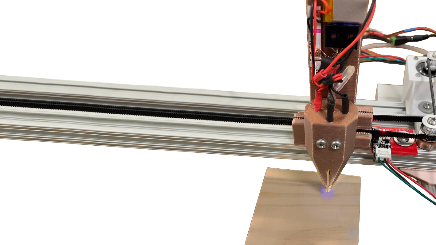
II. Fret Slot Milling
III. Fret Wire Pressing
IV. Fret Cutting
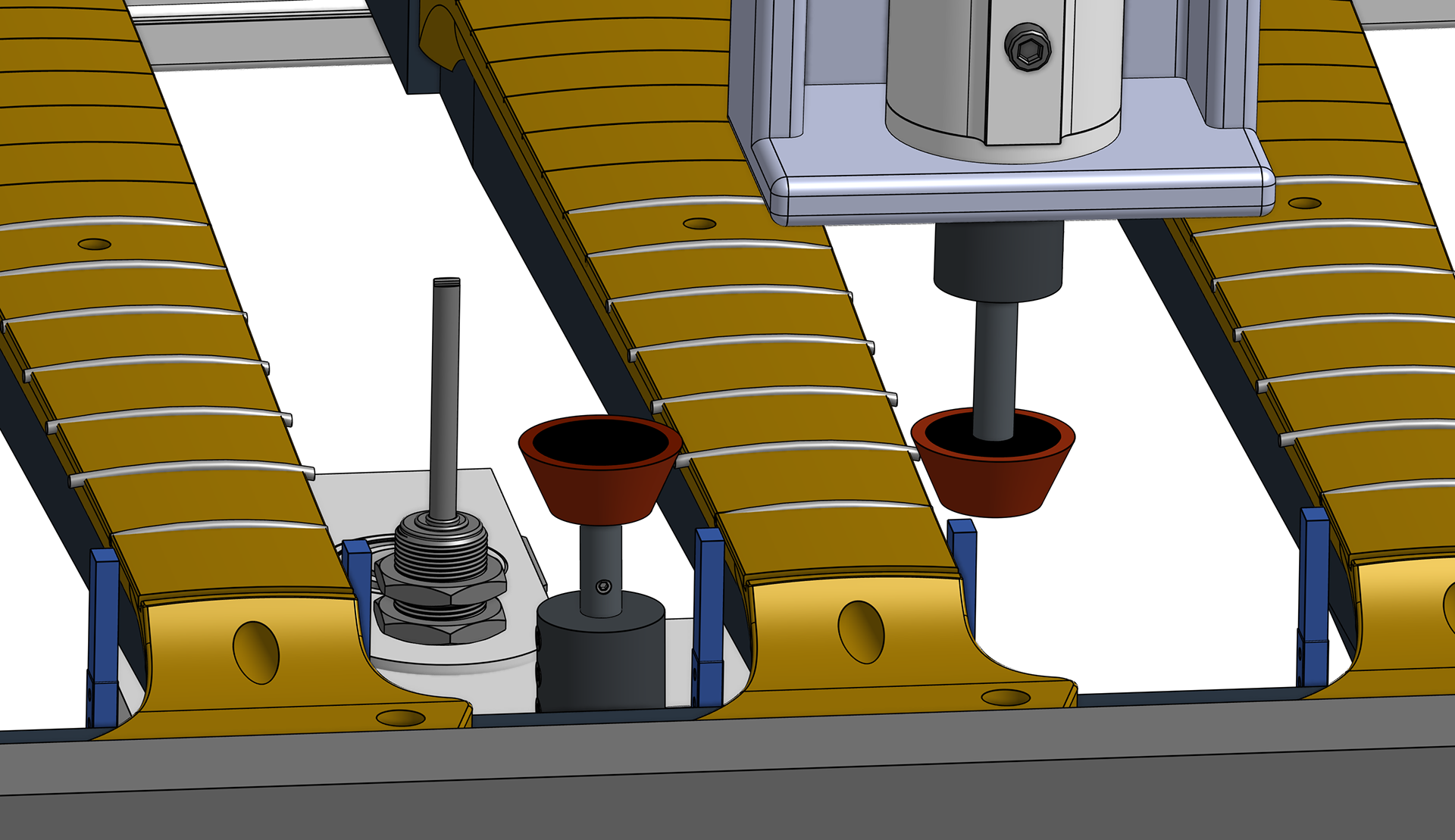
V. Fret Grinding & Polishing
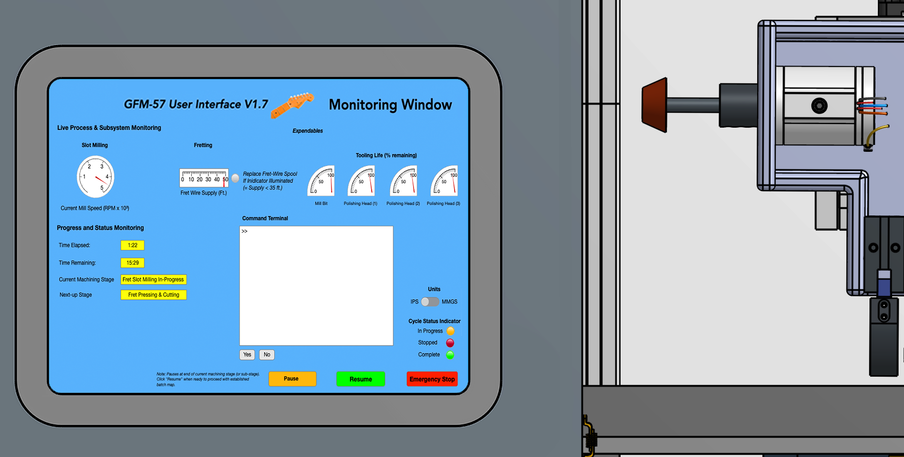
VI. Batch Monitoring
The GUI Batch Monitoring Window provides information on the current cycle status, end-effector RPM, % tooling life remaining, and consumable supplies.
Flow Chart: Controls & Hardware
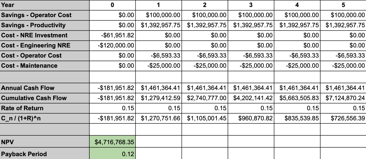
Financial Justification
Our proposed design has a 5-year NPV (net present value) of $4.7M, and a 6-week payback period, making it an excellent investment.
A PDF with the complete FDR presentation for this project, including a complete bill of materials and detailed financial justification (see appendix), motor torque calculations, and other details can be downloaded above under Design Selection.