Project Overview: Part I
The first portion of this project was performed individually. I machined each pump component from raw stock materials, using a range of manufacturing methods, including lathe, 3-axis end mill, CNC, water jet, laser cutter, sand casting, thermal interference fitting, and injection molding. The second portion of this project involved a redesign of the pump fabricated in Part I, to meet a set of simulated specifications and customer requirements, with an emphasis on design optimization for manufacturing (DFM).
Pump components prior to first dry assembly
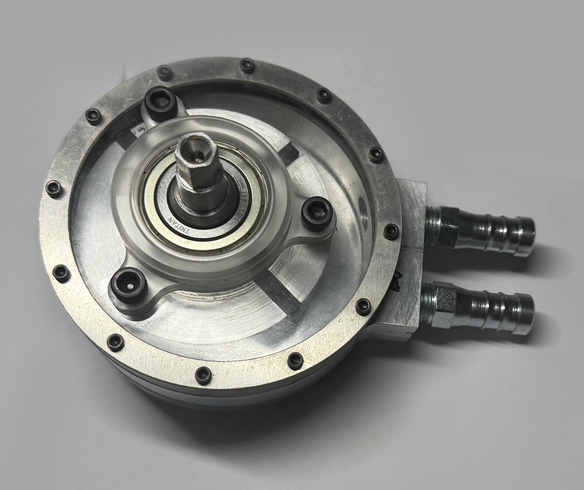
Fully-assembled prototype
Part I: Pump Fabrication
Machining Processes Used in Fabrication
• Lathe • Laser cutter
• CNC • 3-axis end mill
• Water jet cutter • Sand casting
• Injection molding • Shrink fitting
• CNC • 3-axis end mill
• Water jet cutter • Sand casting
• Injection molding • Shrink fitting
A Note on Precision Tolerancing
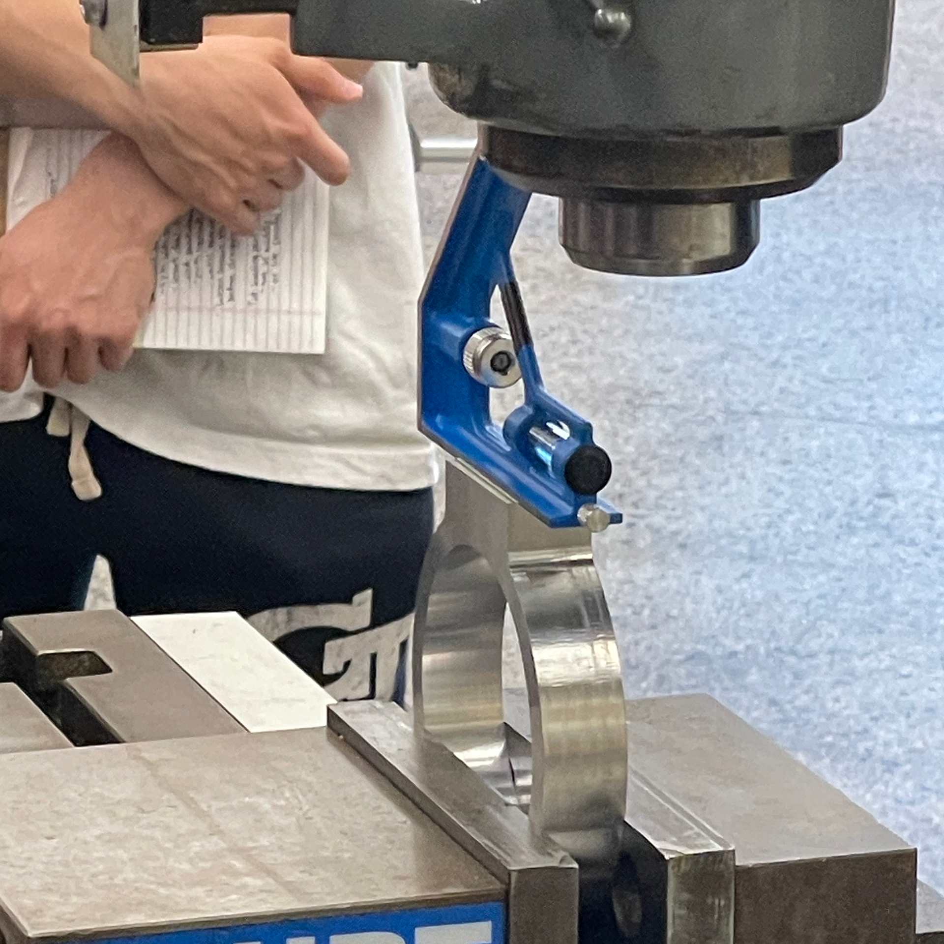
Rotary vane pumps require precise tolerances to function properly. This prevents interference and friction between rotating components, while also allowing for requisite operating pressures to be maintained. For example, the four teflon vanes used in this pump were milled manually to a tolerance of ±0.0005".
Footage of sand casting the bearing housings in aluminum
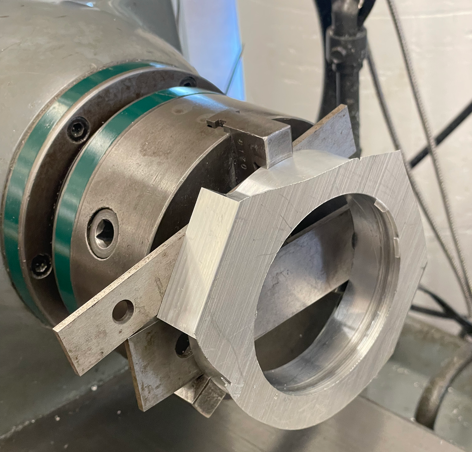
Machining of housing during an interrupted cut on the lathe
Footage of CNC milling of vane slots into rotor after turning on lathe
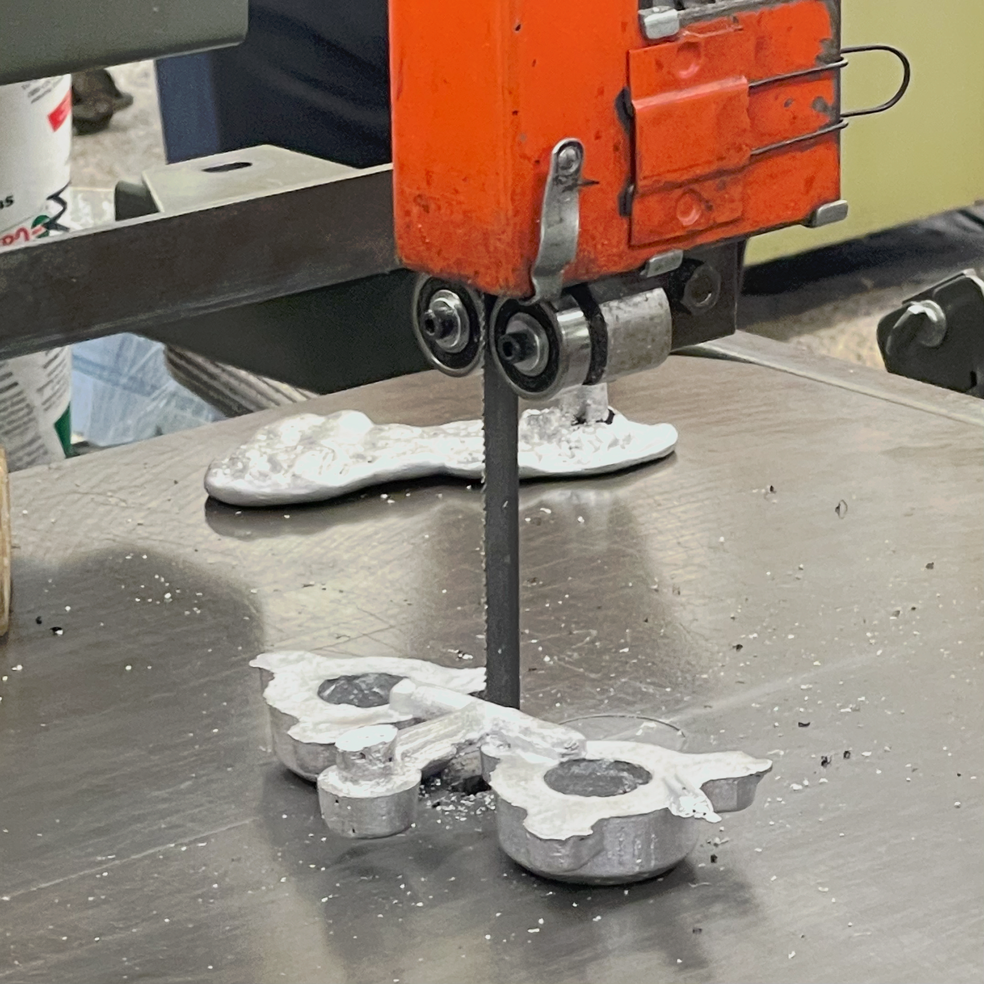
Post-processing of sand cast bearing housings with band saw
Milling of inlet & outlet holes prior to tapping and installation of threaded fittings to housing
Part II: Pump Redesign
Project Overview: Part II
The second part of this project was completed as a group. The pump fabricated in Part I was redesigned to meet a set of simulated operational requirements for pumping polyvinyl acetate in a factory setting.
A DFM (design for manufacturing) approach directed the design process. GT&T was used to communicate the functional requirements of each component, while minimizing costs associated with tolerancing. Mechanical design choices were made in tandem with MFG method and material selections. This approach was aimed at minimizing costs, maximizing longevity, and meeting a specified production throughput.
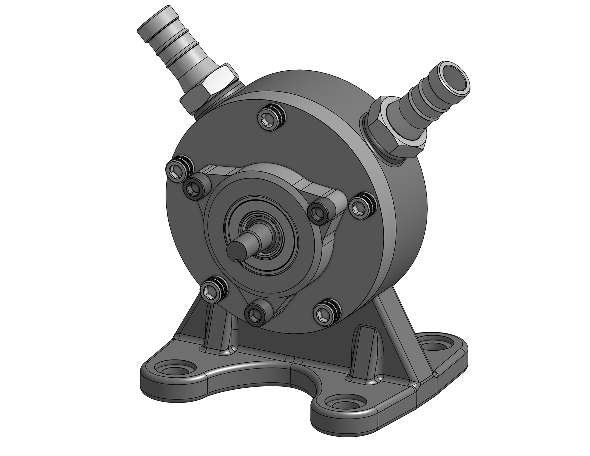
CAD rendering of pump redesign
Design Overview
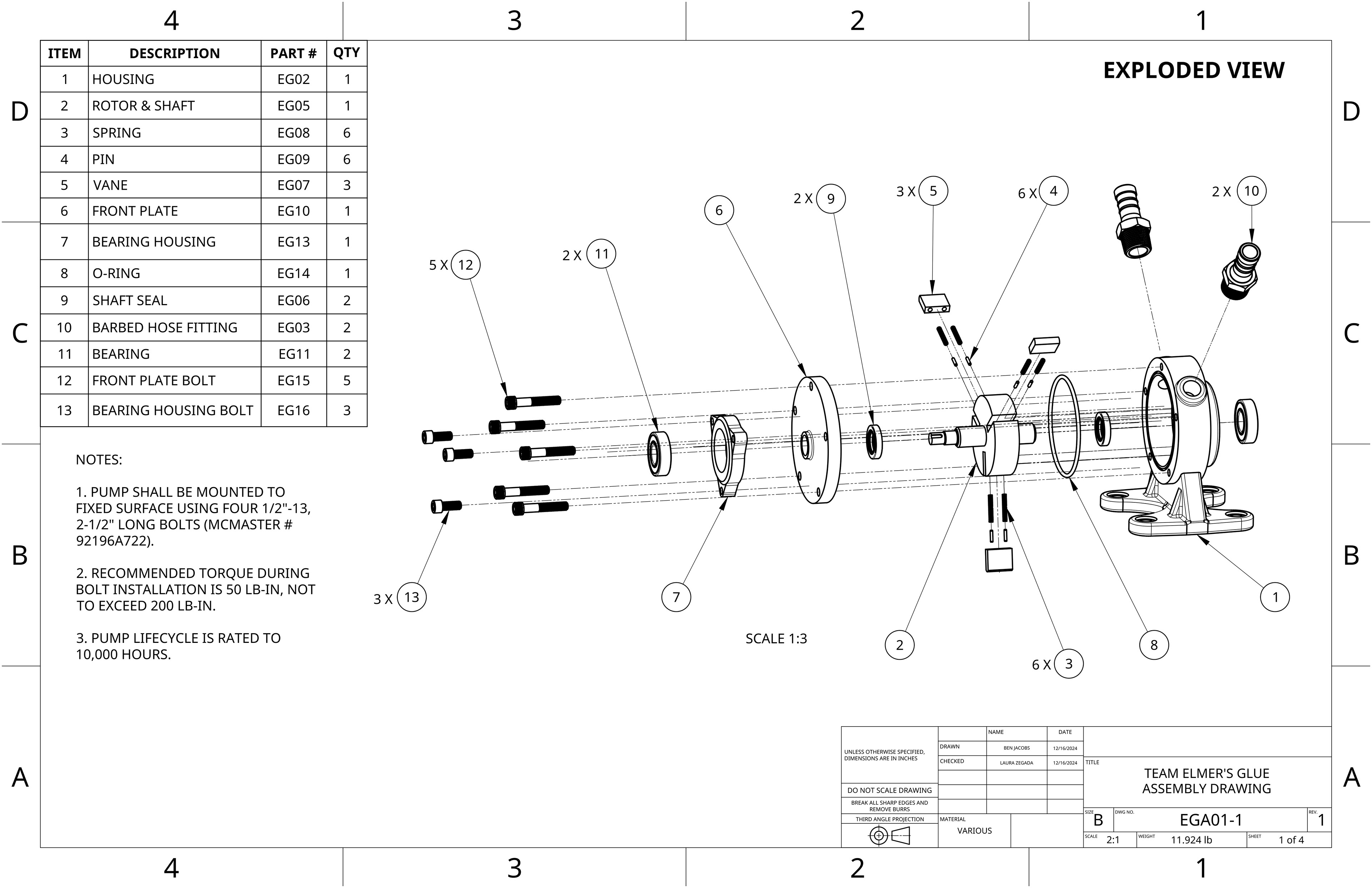
Exploded drawing view of full assembly
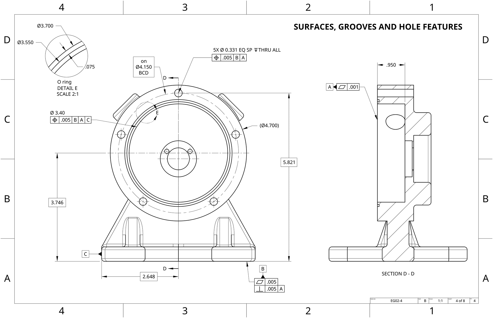
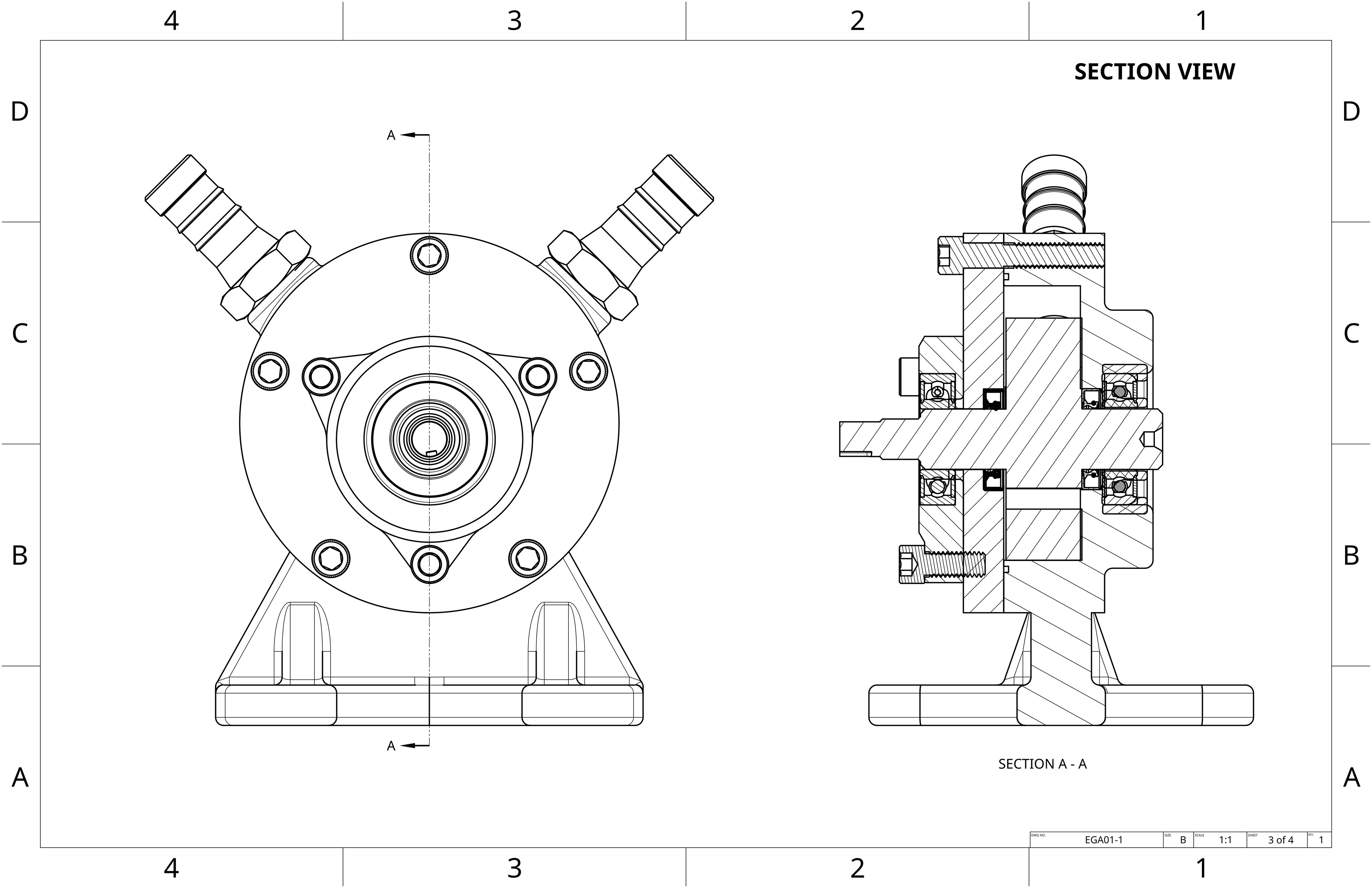
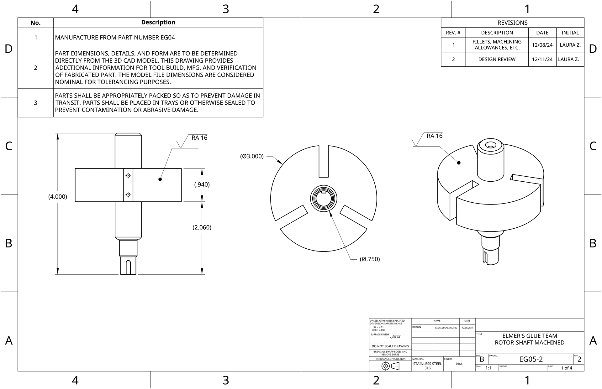
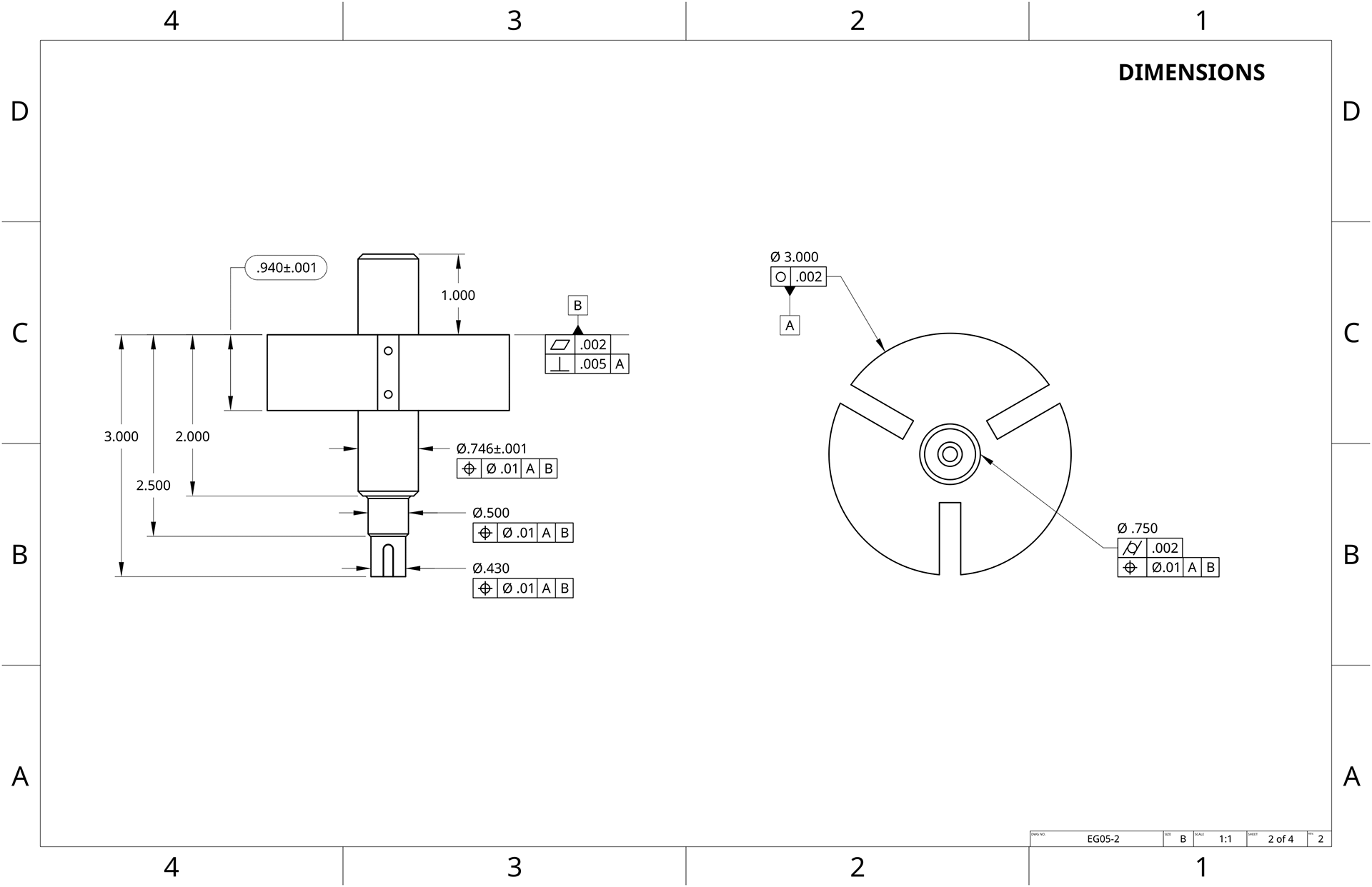
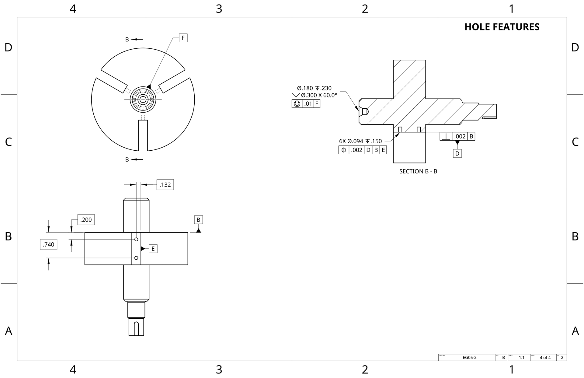
GD&T drawing of housing for machining post-casting
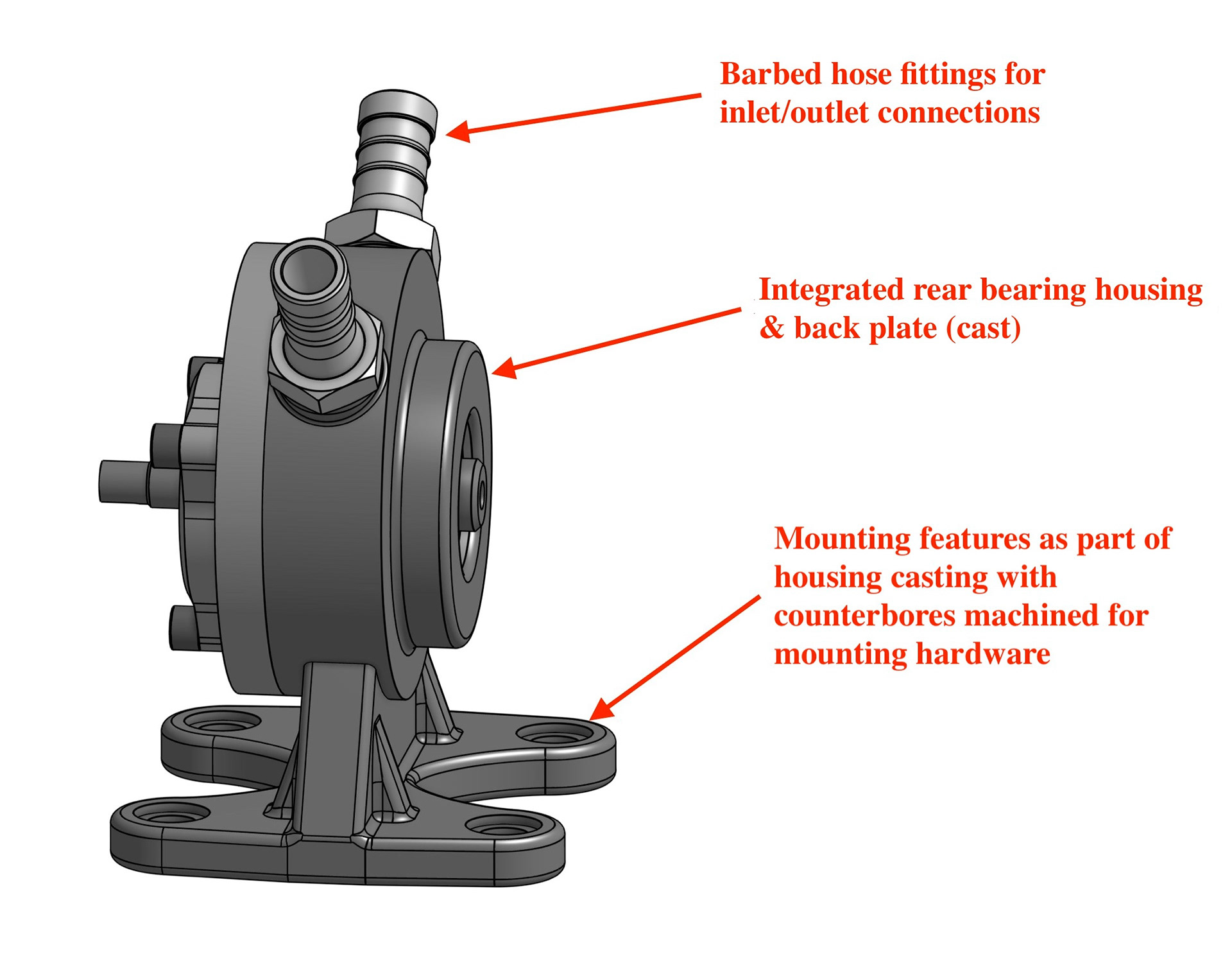
Infographic highlighting several design modifications made to housing
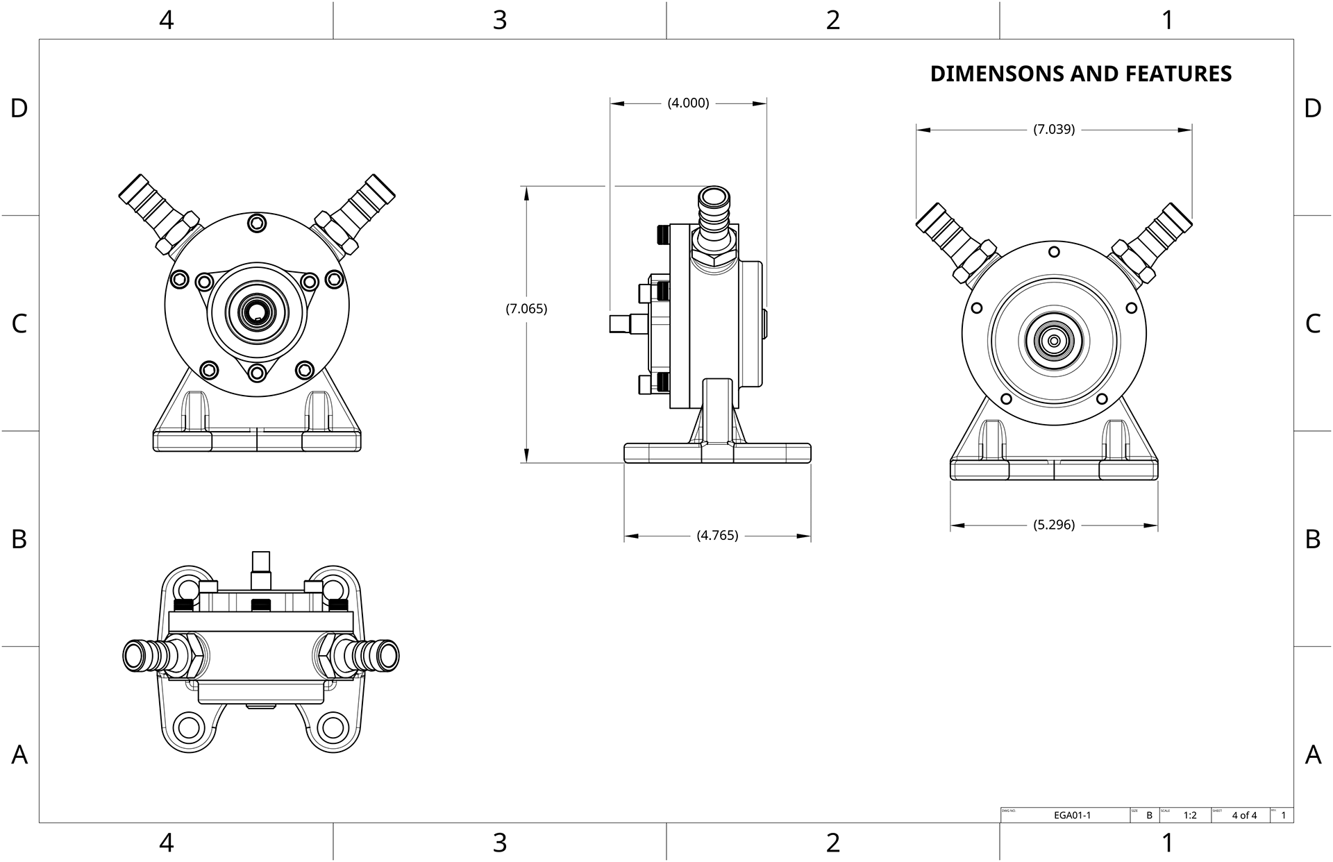
Design Specifications
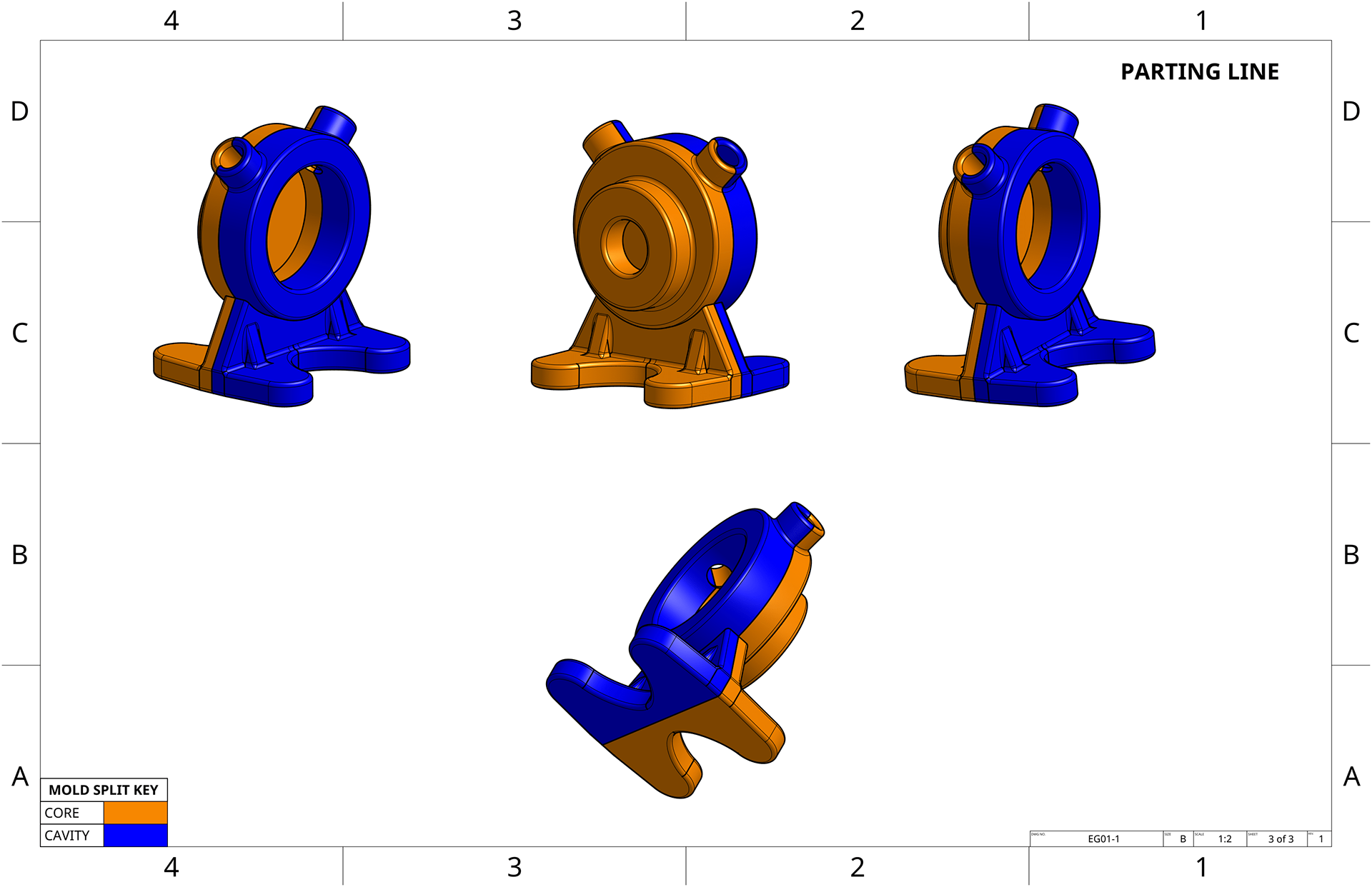
A list of specifications required for the pump redesign is detailed to the right.
Simulated design specifications for pump redesign
Design & Manufacturing Justifications
An efficient engineering team will ensure compatibility between design, material selection, and MFG method. As each manufacturing method poses different constraints and advantages, these factors must be acknowledged early on, starting with the preliminary design phase, and then revisited throughout the development process.
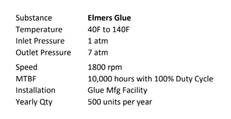
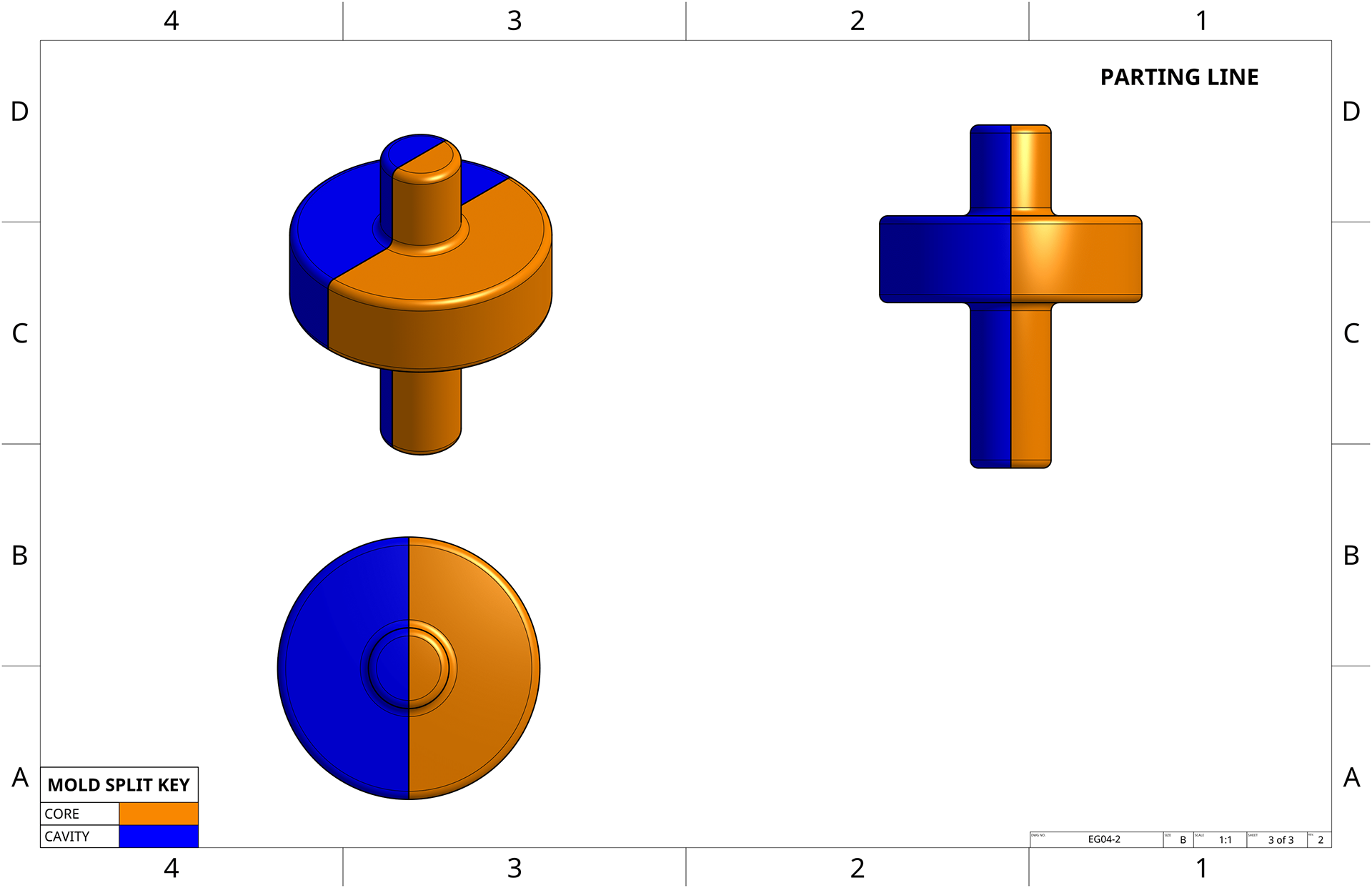
Parting line drawing for housing casting
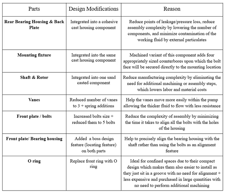
Summary table of design modifications and their justifications
Add 3x1 tiled row with efficient links to PDFs containing: full drawing stack, summary report, assembly manual